Introduction
The aim of the race control box is to have a simple setup that can enable races to be up and running very quickly. The box contains everything needed to run a race.
Description
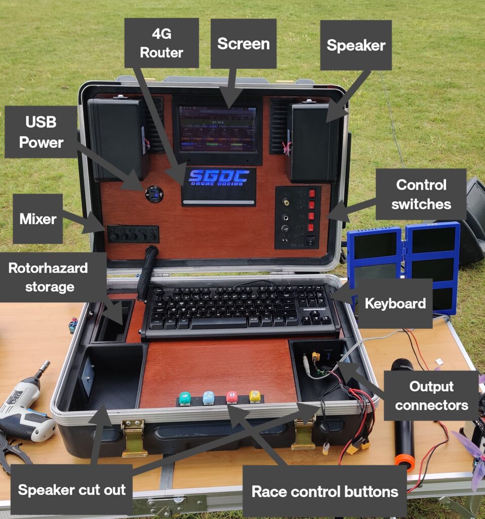
The box contains the following:
- Raspberry pi computer with touch screen and keyboard
- 300W 12V amplifier and speakers
- 4 channel mixer with master volume control
- A chromecast audio to allow streaming music
- 4G router
- Race control buttons for advance, schedule race, stop race, call out pilot names
- USB power and voltage monitor
- Switch panel with main power switch, switches for the main parts, fuse (10A), two audio inputs and battery input
- Output connectors that include audio output, DC output (12V) and USB connection to the PC
- A 10A mains to 12V adapter
Things to Watch out for
- The lid is heavy lower it down gently and watch out for wires going over the edge of the lip and is will cut through them.
- Make sure all mating connectors and adapters are removed from the speaker cut on on the right
- When moving or storing the box be careful of the external connectors and lighting to avoid damage. It is best to not store the box on its end for this reason.
- If use MultiGP make sure the router is switched on before the lap timer (otherwise it will time out when trying to connect to the internet
Usage
Connections
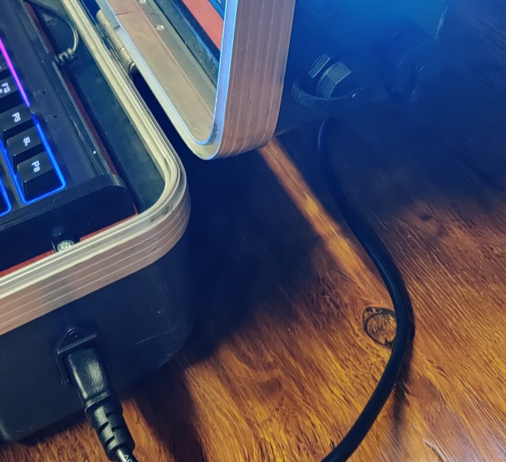
Set the box on a table surface open it up and connect power, either mains in the connector on the side or 12V battery (3S lipo) in the connector on the switch panel.
Switch on the main power to allow the router to boot and connect to the internet
Connect the ethernet to one of the ethernet ports under the waterproof covers and connect the other end to the timer. At the same time connect power to the timer (3S to 6S battery)
Switch Panel
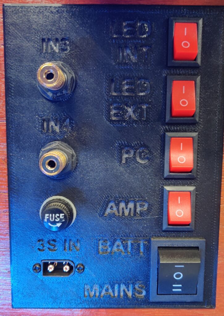
The switch panel contains the following switches:
- Mains power switch - allows selecting mains - off - battery
- Amp power switch - turns the amplifier on or off
- PC power switch - turns the raspberry pi computer on or off
- LED EXT - turns the external LED's on or off, this is the LED's on the side and the LED's down by the race control switches
- LED INT - turns the internal LED's on or off, this it the blue SGDC logo in the middle of the case
The following is powered on all the time ones the main power switch is on
- the 4G router
- The audio mixer
- The chromecast audio
Additionally the switch panel has the following:
- 3S IN - Power input for a 3S (12V) power input, only use a 3S battery on this input (10.5V to 12.6V) anything outside of this range may cause damage
- Fuse - A 10A slow blow 5x20mm fuse
- IN3 & IN4 - These audio inputs connect to IN3 and IN4 on the mixer, this allows you to connect things like laptop, phone or microphone. The connector is a 6.35mm stereo jack but should have a 3.5mm adapter in each.
Note that if you connect a device to IN3 & IN4 and also into the USB charging ports you will create a ground loop which will prevent the sound output
Mixer
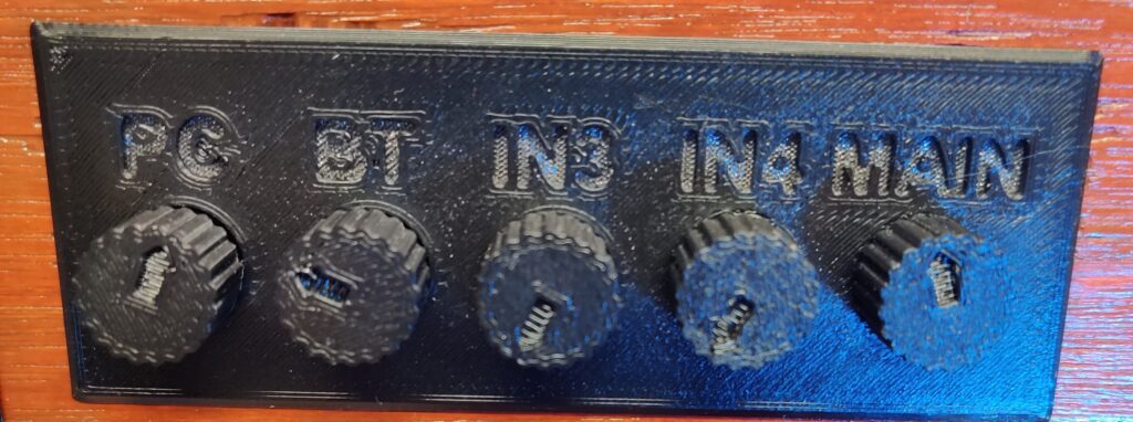
The mixer controls the volume of 4 inputs and has a main volume out, the dials do the following:
- PC - Controls the volume of the timing PC output
- BT - Controls the volume of the chromecast output
- IN3 & IN4 - Controls the volume of the IN3 & IN4 input jacks on the switch panel
- MAIN - Is the main output volume from the mixer
When using an external source such as audio streaming on the chomecast or IN3 or IN4 be mindful that the devices volume will affect the total output volume.
To use the chromecast audio connect to the WiFi and then you will have the option to stream from music apps like spotify or google music. You should also be able to cast your whole phone screen
Output Connectors
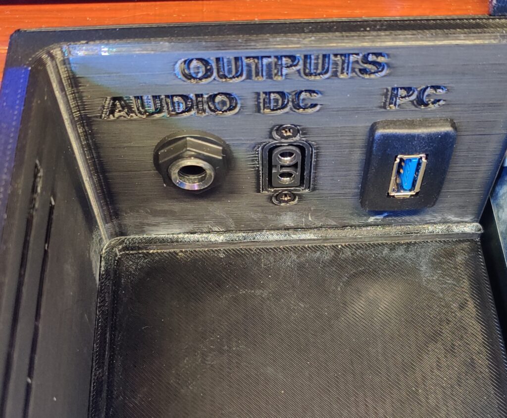
In the right hand side speaker cut out there are 3 OUTPUT connectors with the following functions:
- AUDIO - Is the audio output from the mixer
- DC - Output of the main power supply (either the 12V from the mains adapter or from the battery), do not exceed about 5A total current draw otherwise you may blow the fuse.
- PC - A USB connector to the pi to allow things like mice of cameras to be connected
USB Charger
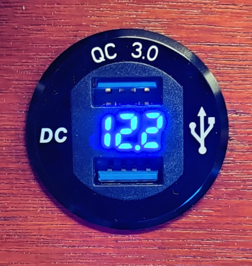
The USB charger can charge two USB devices, note the 5A limit mentioned on the DC output above should also take into account these outputs
The charger also has a voltage display that shows the voltage of the main power so any lipo power can be monitored.
Computer
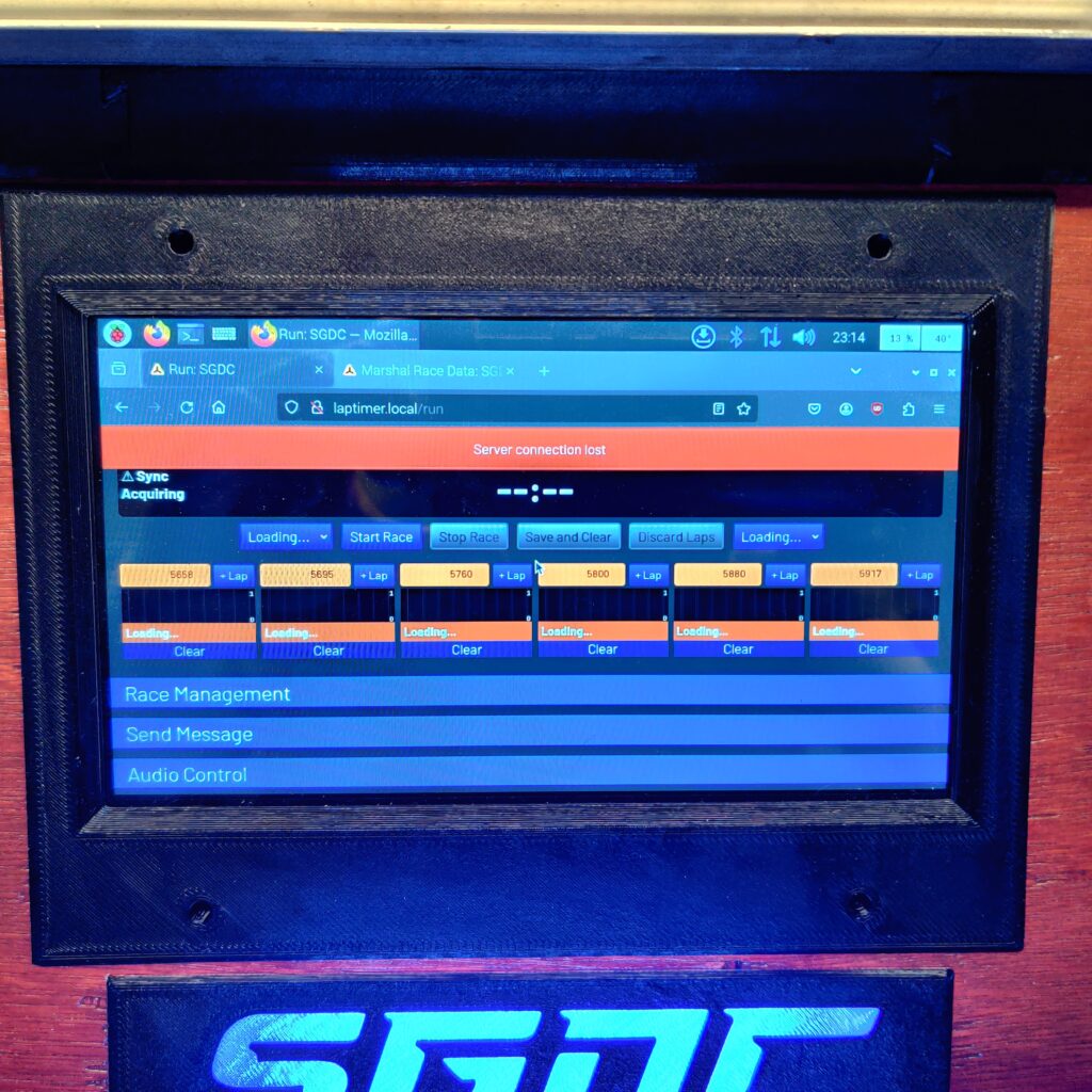
The computer is a Raspberry pi 4, it will boot up automatically and open the browser connection to the laptimer when it boots up.
The computer is a touch screen with additional keyboard to make to make data entry easier.
It is probably best to shut the computer down before turning off but it should be ok to remove power as the PC has its system files protected.
Temperature an CPU usage are show in the top right of the screen
Scrolling can be a little fiddly in the web browser you need to run your finger down the right hand side of the screen (the best technique is to have your nail facing into the center of the screen. You can also use the arrow keys on the keyboard.
Race Control Keys
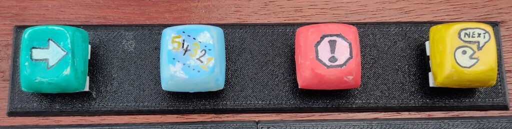
There are 4 race control keys that work when the timer is on the run page on the PC from left to right the keys d the following:
- Advance race - Start race, stop race, save and clear race
- Schedule race - Starts the scheduled race countdown to give you time to sit down
- Stop race - Stops the race
- Call out - Calls out the pilots up next
The above buttons simulate a keyboard so it is important to make sure you don't have a typing dialogue open as you will enter letters into associated with the above shortcuts
Connection Information
To connect your device to the system you can either use the Ethernet ports or connect via WiFi. Your device will need to work on 5.8 GHz. The connection info is:
- SSID: RaceControl
- Password: <See sticker on Race control box>
- To connect to the laptimer interface you can use the address laptimer.local
- The chromecast name is Race Control Music
The 4G router status lights can be seen (in darker conditions) in the transparent strip under the SGDC logo